By reading the following you will learn about rigid flex circuit boards benefits, applications, related design considerations, and FC rigid flex PCB capabilities.
FC Rigid Flex PCB Display
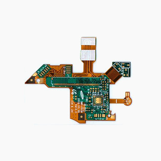
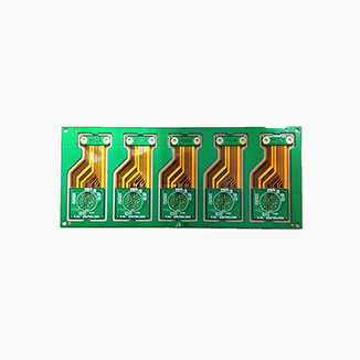
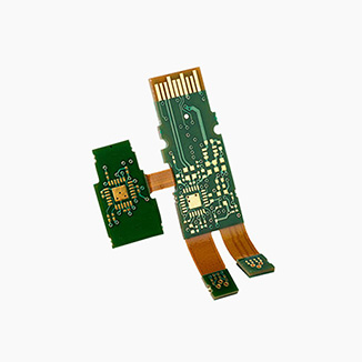
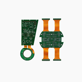
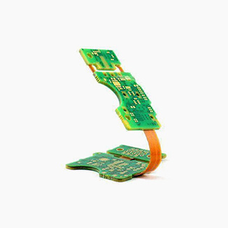
What is a Rigid Flex PCB?
Rigid-Flex PCB is a circuit board composed of one or more rigid areas that provide structure and flexible areas that allow bending and folding. Integrating rigid and flexible substrates into one unit combines the advantages of rigid and flexible circuit boards, allowing the circuit board to fit into complex spaces while ensuring functionality and reliability.
Advantages of Rigid-Flex PCB
Space Efficiency
Enhanced Reliability
Increased Durability
Save Cost
Design Flexibility
Rigid flex circuit boards have several advantages over traditional rigid PCBs
- Space optimization: The compact design of rigid flex PCBs significantly improves space efficiency. They reduce the reliance on additional interconnect components by removing the need for connectors, allowing for more compact electronic device designs. In addition, these PCBs can be flexibly folded or bent to fit into tight spaces, making them ideal for space-constrained electronics.
- Enhanced Reliability: Rigid flex boards reduce the number of connectors in a system, which reduces the number of points of failure and improves system stability and reliability. Rigid-flex PCBs provide a more robust solution to connectivity than traditional connectors, reducing the risk of system failure due to connector issues.
- Increased Durability: Rigid flex circuit boards are specifically designed to withstand mechanical stress, vibration, and temperature fluctuations, making them ideal for use in harsh or demanding applications.
- Cost Effectiveness: While the manufacturing process for rigid-flex circuit boards may be technically more complex, they can often reduce the number of components and manual assembly steps required, resulting in savings in overall assembly costs.
- Design Freedom: Rigid-flex technology offers designers the possibility to create complex board shapes and three-dimensional layouts that are often difficult to achieve in traditional PCB design, providing more room for innovation in the design of electronic products.
Rigid-flex PCB Design Consideration:
The design of rigid flex circuit boards requires consideration of several key factors to ensure the performance, reliability, and manufacturability of the final product. Below are some of the key design considerations:
- Material Selection: Select suitable flexible and rigid substrate materials such as polyimide (PI), liquid crystal polymer (LCP), or FR-4, which should have good mechanical properties and thermal stability. Consider the type of adhesive to ensure a strong bond between the flexible and rigid parts.
- Bending radius: Determine the minimum bending radius of the flexible part to avoid material fatigue and cracking. Design to avoid sharp bends and excessive flexing to extend product life.
- Laminate structure: Optimize the laminate design to provide adequate mechanical strength and electrical performance. Consider signal integrity, impedance control, and electromagnetic compatibility (EMC).
- Component Placement: Place heavy or large components in rigid areas to avoid unnecessary stress on flexible substrates. Avoid placing components in areas where flexing is expected.
- Wire routing: Avoid sharp corners and tight bend radii in flexible areas. Ensure that wire widths and spacing are appropriate for bending and electrical performance requirements.
- Thermal Management: Consider coefficient of thermal expansion (CTE) matching to minimize thermal stress.
Design effective heat dissipation paths to prevent overheating. - Signal integrity: Optimize cabling to reduce signal attenuation and interference. Use impedance matching and shielding techniques to improve signal integrity.
- Power and ground planes: Design power and ground planes in rigid areas to provide stable power distribution and signal referencing.
- Connector design: Select connector types that are suitable for rigid flex circuit boards, such as FPC/FFC connectors or board-to-board connectors. Add reinforcement around the connector to improve mechanical stability.
- Manufacturing process: Consider lamination, drilling, plating, and assembly techniques for the manufacturing process.
Ensure the design meets the manufacturer’s capabilities and limitations. - Testing and Inspection: Plan a test strategy that includes electrical testing, visual inspection, and functional testing. Ensure that test points and boundary-scan structures are included in the design.
- Cost Effectiveness: Balance design complexity with cost-effectiveness. Consider the impact of the design on manufacturing costs, material costs, and assembly costs.
- Environmental Factors: Consider the environment in which the product will operate, such as temperature, humidity, chemicals, and mechanical stress. Select materials and designs that can withstand these environmental conditions.
- Reliability and Durability: Ensure that the design can withstand the expected mechanical and environmental stresses.
Perform necessary life tests and reliability analyses.
By considering these factors, designers can ensure that rigid flex boards meet specific application requirements and provide superior performance during production and use.
Rigid Flex PCB Applications
Aerospace & Defense
Medical Devices
Automotive Electronics
Consumer Electronics
Industrial Automation
Rigid flex circuit boards are used in a wide range of applications, here are some areas of specific applications and their advantages:
- Aerospace and defense: Rigid flex PCBs are used in aircraft avionics systems such as flight control systems and communications equipment due to their heat and vibration resistance. In satellites, rigid-flex PCBs are used to manage power and signal distribution while reducing weight and improving energy efficiency. Equipment in military applications, such as radar and communications equipment, utilize the high reliability and durability of rigid-flex boards.
- Medical devices: such as health monitoring equipment, utilize the flexibility and compactness of rigid-flex PCBs to design devices that fit comfortably and snugly into the body. Examples include pacemakers and neurostimulators, utilizing the miniaturization and biocompatibility of rigid-flex PCBs. Surgical robots and precision medical devices use rigid-flex circuit boards for high precision and flexibility.
- Automotive electronics: such as engine management systems, utilizing the high temperature and vibration resistance of flexible rigid PCBs. For safety systems such as airbag deployment and braking systems, Rigid-Flex boards provide stable signal transmission. In automotive infotainment systems, Rigid flex PCBs help to achieve complex space layouts and compact designs.
- Consumer electronics: Rigid flex circuit boards allow devices to be thinner while providing high performance and good signal transmission. In tablets, flexible rigid PCBs help achieve large screens and thin designs. Smartwatches and health trackers, for example, utilize the flexibility of rigid-flex PCBs to provide a comfortable wearing experience.
- Industrial automation: Control systems and sensors in robots use flexible rigid PCBs to accommodate the bending and twisting of moving parts. In machine vision, rigid-flex PCBs are used in high-speed cameras and image processing units to provide stable image transmission and processing capabilities. In chemical and manufacturing processes, flexible rigid PCBs are used in sensors and controllers for precise process control.
These applications demonstrate the versatility and importance of flexible rigid PCBs in the design of modern electronic devices. As technology continues to advance, the use of rigid-flex PCBs in a variety of fields will become even more widespread.
FC Rigid-flex Board Capabilities
| Rigid-flex pcb | Manufacture capacity |
| Layer Counts | 1-8Layer |
| Base Material | Polyimide/FR4 |
| Copper foil thickness | 1oz / 1/2oz/ 1/3oz |
| PI thickness | 25μm / 12.5μm |
| Board thickness | 0.07mm-0.5mm |
| Adhesive | 13μm |
| Max. board size | 400*800 mm |
| Product thickness tolerance | ±0.03mm |
| Min. Hole Diameter | 0.1mm |
| Min. Line Width / Distance | 0.04mm |
| Etching tolerance | ±0.015mm |
| PTH Hole dia. tolerance | ±0.03mm |
| NPTH Hole dia. tolerance | ±0.05mm |
| Outline Dimension tolerance | ±0.075mm |
| Stiffener material type | ±0.075mm PI / FR4 / PET / Steel piece |
| Outline profile | Punching / Laser cut / Drilled |
| Surface finish | HASL / OSP / ENIG / Immersion silver / Tin / Ni |
| Solder mask color | Multi-color |
| Silkscreen color | White/Black |
| Acceptable file format | CAD / Gerber file / powerpcb / AutoCAD / P-cad / CAM-350 / |
FC - Fast Turn Rigid Flex PCB Manufacturer
FC has many years of experience in PCB manufacturing and assembly and is committed to providing high quality PCB service. Whether it is small batch production or large batch production, we always pursue high quality and fine service. If you are interested in our rigid flex PCBs, feel free to contact us.