
In the development of cutting-edge materials for high-frequency PCBs, Rogers Corporation is a pioneer. These cutting-edge materials, referred to as Rogers PCB materials, have revolutionized the electronics sector by making it possible to design very effective high-frequency circuits.
The various kinds of Rogers PCB materials, their characteristics, comparisons with FR4, stackup configurations, manufacturing processes, and their applications in various industries will all be covered in this article.
What is Rogers PCB?
The term "Rogers PCB" describes PCBs that are constructed using unique materials sold by Rogers Corporation rather than the standard FR-4 material. Unlike traditional FR4 PCBs, Rogers materials offer lower dielectric loss, better thermal management, consistent dielectric constant, and superior signal integrity, which make them ideal for RF, microwave, and fast digital applications, such as RF (radio frequency), microwave, and aerospace systems. Their features include:
High Thermal Conductivity

Consistent Dielectric Constant
Better Impedance Control
Lower Dielectric Loss
Superior Signal Integrity
Rogers PCB Types
Rogers Corporation provides a variety of PCB materials, each suited for specific applications. Here are some of the most common Rogers PCB types:
RO3000
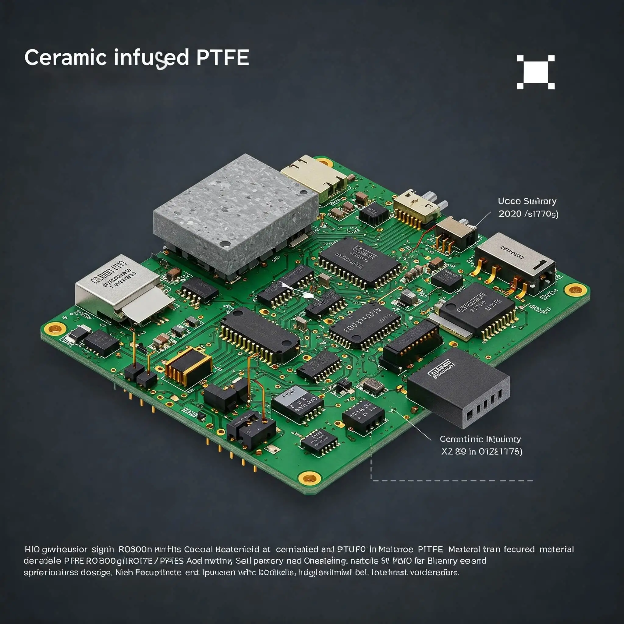
Ceramic-infused PTFE (a kind of plastic) materials are part of the RO3000 series. These materials offer numerous alternatives ideal for varied high-frequency PCB design needs.
- RO3003: Perfect for uses where very low dielectric loss is required.
- RO3006: High-frequency and high-reliability applications employ the RO3006 device.
- RO3010: Advanced microwave designs use RO3010, a high dielectric constant (Dk) material.
RO4000
Due to its reduced energy loss, RO4350B performs better than conventional circuit materials in high-frequency applications. With a range of 0.6 to 0.8, this series has superior heat conduction compared to most. It performs better for microwave or radio frequency communications and it provides DK values ranging from 2.55 to 6.15.
- Rogers RO4350B is among the best materials for high-frequency PCBs. It facilitates the creation of circuits for RF engineers with tools such as accurate network matching and control over the resistance of the transmission line.
- RO4003C: Often used in RF/microwave applications, this series offers great frequency stability and minimal loss.

Rogers RT/duroid®
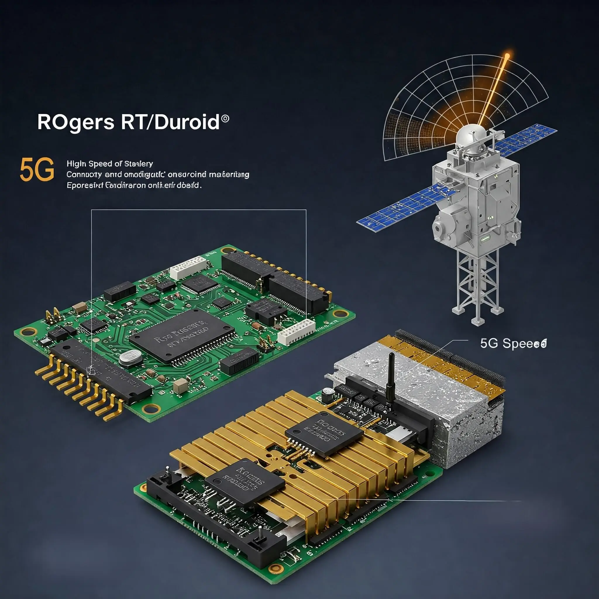
Applications including 5G, satellite communications, radar systems, and high-speed radio frequency circuits all make extensive use of these materials.
- RT/duroid 5880 is a popular low-loss, low-Dk material for radar systems and antennas.
- RT/duroid 5870 is comparable to 5880 but has a slightly different dielectric constant.
- RT/duroid 6002: Economical PTFE. Compared to FR4, it has superior heat conductivity.
- RT/duroid 6202: The dielectric constant for the RT/duroid 6202 is a steady 2.94. It operates at up to GHz. minimal loss of electricity. There is little moisture absorption.
TMM®
The Rogers Corporation TMM series is a range of microwave and RF PCB materials with high performance. It is ideally suited for RF circuits, microwave components, and antenna systems.
- TMM10: Offers dielectric constant 9.2 with low loss and stable RF and microwave characteristics.
- TMM13: With a higher dielectric constant of 12.85, it is ideal for dense designs that require precise impedance control in high-frequency circuits.

Difference Between Rogers Materials and FR-4 Materials
The way that FR-4 and Rogers materials transport heat and electricity is one of their main differences.
Rogers laminates' low and constant dielectric constant, minimal energy loss, and effective heat management make them ideal for high-frequency and radio-frequency applications.
Additionally, they have improved their resistance management and moisture absorption, which results in little signal loss in difficult-to-reach places like microwave circuits, 5G, and aircraft. Although FR-4 is a popular and reasonably priced PCB material, it loses more energy and is less stable at high frequencies.
Even though it functions well in conventional electrical circuits, issues such as unequal resistance and signal loss make it less effective in microwave and radio frequency (RF) systems. Furthermore, FR-4 is less efficient at dissipating heat than Rogers materials because it transfers heat less well.
|
Feature |
Rogers PCB |
FR4 |
|---|---|---|
|
Dielectric Constant |
Low and stable |
Higher and less stable |
|
Signal Loss |
Minimal |
Higher |
|
Thermal Conductivity |
Better |
Lower |
|
Cost |
Higher |
Lower |
|
Applications |
High-frequency, RF, microwave |
Consumer electronics, low-speed designs |
If your project involves high-frequency signals or requires superior thermal performance, Rogers PCB boards are the way to go. For cost-sensitive, low-frequency applications, FR4 remains a reliable choice. Of course, you can combine Rogers and FR4 layers to balance performance and cost in some cases.
Rogers PCB Board Fabrication
Since the materials of Rogers PCBs contradict conventional FR-4, particular production techniques must be applied.
Material Selection:
The appropriate Rogers laminate should be selected based on the requirements for heat, frequency, and strength. (e.g., RO4350B for wireless systems or RT/duroid 5880 for aerospace).
Lamination:
The materials used in Rogers technology require controlled temperature and pressure through the lamination process to prevent deformation, unlike FR-4.
Drilling and Plating:
Precise drilling is used to create vias, which are then plated with copper to create electrical connections.
Etching and Imaging:
The copper is removed carefully in order to produce exact circuit routes.
Solder Mask:
A solder mask is applied to protect the circuitry and prevent short circuits from occurring.
Surface Finishing:
Organic Solderability Preservative (OSP) and Electroless Nickel Immersion Gold (ENIG) are commonly used surface finishes that improve solderability and protect the integrity of copper traces.
Inspection and Testing
Rigorous testing (e.g., impedance testing, thermal testing) is conducted to ensure the PCB meets performance standards.
Final Assembly
Components are mounted onto the PCB using surface-mount technology (SMT) or through-hole technology (THT).
Applications of Rogers PCB Board
- RF and Microwave Circuits: Utilized in radar systems, antennas, and satellite communication.
- Wireless communication with 5G: Provide faster transmission with reduced signal loss.
- Automotive and Aerospace: The automobile and aviation sectors are essential to the development of advanced driver assistance systems (ADAS) and aircraft technology.
- High-Speed Digital Applications: Reliable performance in networking and telecommunications devices is ensured by quick digital applications.
Factors to Consider While Designing Rogers Circuit Boards
- Material Selection: Depending on your needs for frequency and heat, choose the appropriate Rogers laminate.
- Matching Impedance: Make sure the pathways are carefully designed to have a consistent impedance.
- Layer Stackup: Verify that the Rogers material you have selected is compatible with common PCB manufacturing techniques.
- Performance vs. Cost: Strike a fair balance between the cost and functionality of the materials to create the finest design.
Conclusion
Due to their excellent electrical and thermal characteristics, Rogers PCBs are the ideal choice for high-frequency, radio-frequency, and microwave applications. Understanding the subtleties of these sophisticated materials will enable you to make wise selections for your next project, whether your project involves Rogers 4350B, complicated stack-up design, exploration of several Rogers PCB kinds, or search for a reliable Rogers PCB manufacturer.
So, if you are making RF circuits, systems for aerospace, or advanced communication gadgets, choosing the right PCB supplier helps you achieve the best results. FC PCBA focus on making high-quality Rogers circuit boards with careful engineering and expert support. Get in touch with us today to talk about your project and get a solution that fits your specific needs.
Frequently Asked Questions
What explains the popularity of Rogers 4350B across Rogers materials?
The typical uses of Rogers 4350B in wireless communication systems, automotive radar, and satellite technology are explained below. Rogers 4350B is known for:
- Low Dielectric Constant (Dk): Keep low at 3.48 ± 0.05 at 10 GHz, thus maintaining signal consistent.
- Low Loss Tangent: 0.0037 at 10 GHz, minimizing signal loss in high-frequency applications.
- Exceptional Thermal Stability: Especially appropriate for conditions with temperature variations.
- Mechanical Strength: Provides strength and dependability in demanding situations.
How much does a Rogers PCB cost?
The cost of Rogers PCBs is higher than that of FR4 due to the use of high-end materials and processes. Additionally, the cost varies with the material type, number of layers, and design complexity.
What are the common types of Rogers PCB materials?
Common kinds include the RO4000® series (e.g., RO4350B), RO3000® series (e.g., RO3003), RT/duroid® series (e.g., RT/duroid 5880), and TMM® series (e.g., TMM10, TMM13).
Can Rogers PCB Boards be mixed with FR4 in a stackup?
With Rogers layers employed for high-frequency signal integrity, hybrid stackups mixing Rogers and FR4 materials are often prevalent to balance performance and cost.
Can Rogers circuit boards be used in 5G technology?
Indeed, Rogers PCBs are extensively applied in 5G infrastructure since their low signal loss and high-frequency performance.